Operation Test
6. Have hydraulic valve “D” open. Close valves “M’ and
“N”. Open vacuum valve “E” to source of vacuum. Adjust
vacuum regulating bleeder valve “R” to obtain 20” of vacuum
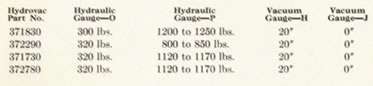
at gauges “H” and “J”. Turn pressure screw “F”
down until gauge readings specified in the following chart are obtained. Then
fully release pressure screw “F”. All hydraulic gauges should read
zero and both vacuum gauges read the srme maximum vacuum in the released position.
Vacuum Leakage Test
Released Position
Back pressure screw “F” all the way out. Open vacuum valve
“E” until maximum vacuum is registered on gauges “H”
and “J”, then close valve “E”. Vacuum drop should not
be more than one inch in fifteen seconds.
Applied Position
Now open vacuum valve “E” and turn pressure screw “F”
in until vacuum gauge “J” reads zero. Close valve “E”.
Vacuum registered on gauge “H” should not drop more than one inch
in fifteen seconds,
Hydrovac Air Cleaner Service
The air cleaner used with a Hydrovac Unit is installed in a position on the
chassis affording greatest protection from road dust and splash and is connected
to the power unit by a length of hose.
A clogged air cleaner will prevent the vacuum power brake from ap plying quickly
and for that reason, the air cleaner should be removed from the chassis and
cleaned at frequent intervals.
To disassemble air cleaner—
1. Remove air cleaner cover screw.
2. Remove hair and screens and wash same thoroughly in gasoline.
3. Dry hair and then saturate with light engine oil.
4. Disconnect air cleaner hose at Hydrovac and blow out dirt through air cleaner
shell.
5. Clean air cleaner shell and cover.
6. Replace hair and screen in air cleaner shell and reassemble.
Page <22>